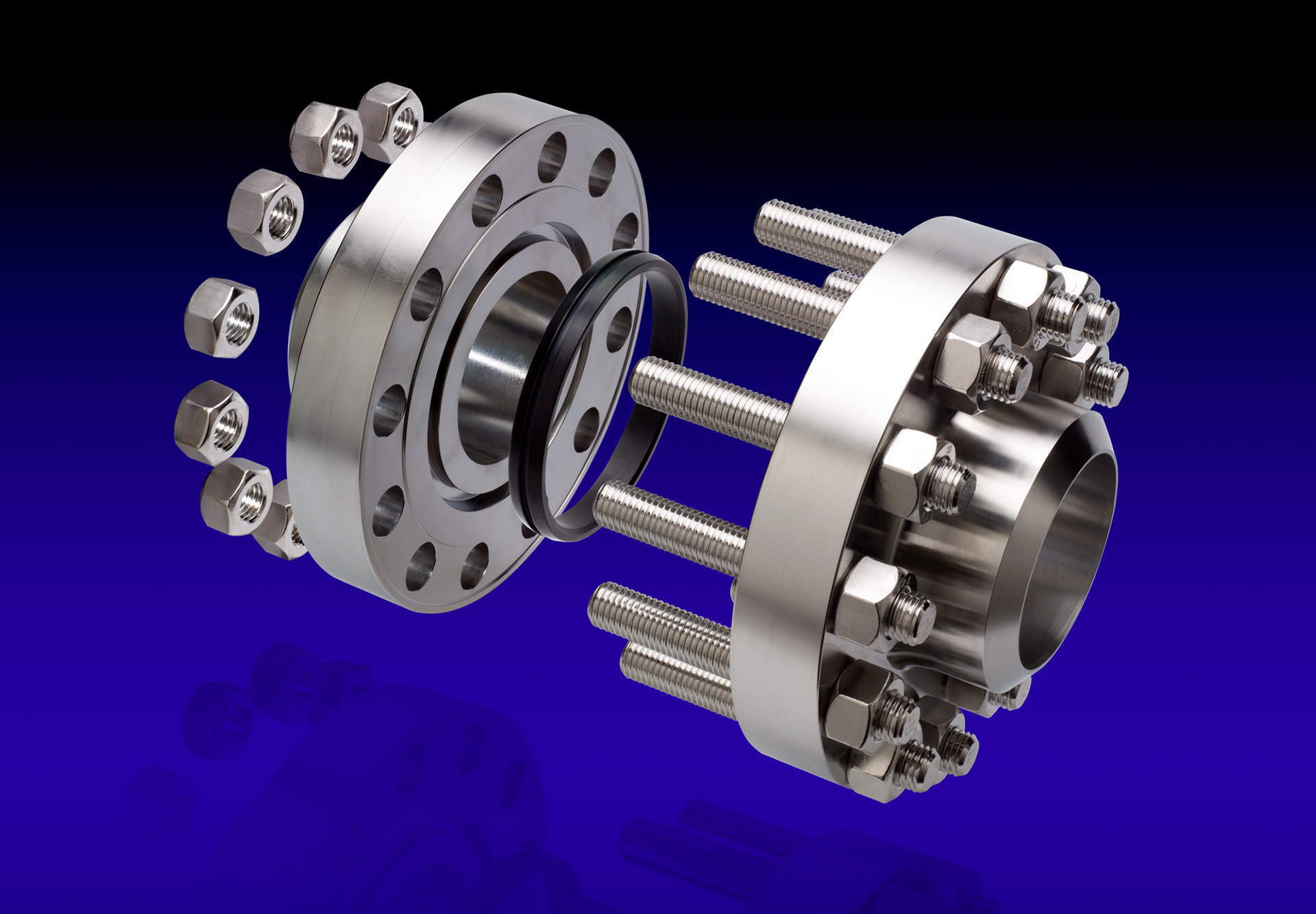
This type of flanged connector is used in the oil and gas industry where connections must be of the highest integrity. Very volatile gases and liquids at pressures up to 17,000 psi have to be contained, and failure is not an option!
This was a fun project to photograph. Thankfully, this was not the largest flange in the client's range. Fully assembled, this one could be lifted by a very strong person. One single flange on its own could be lifted, with care, by the average person.
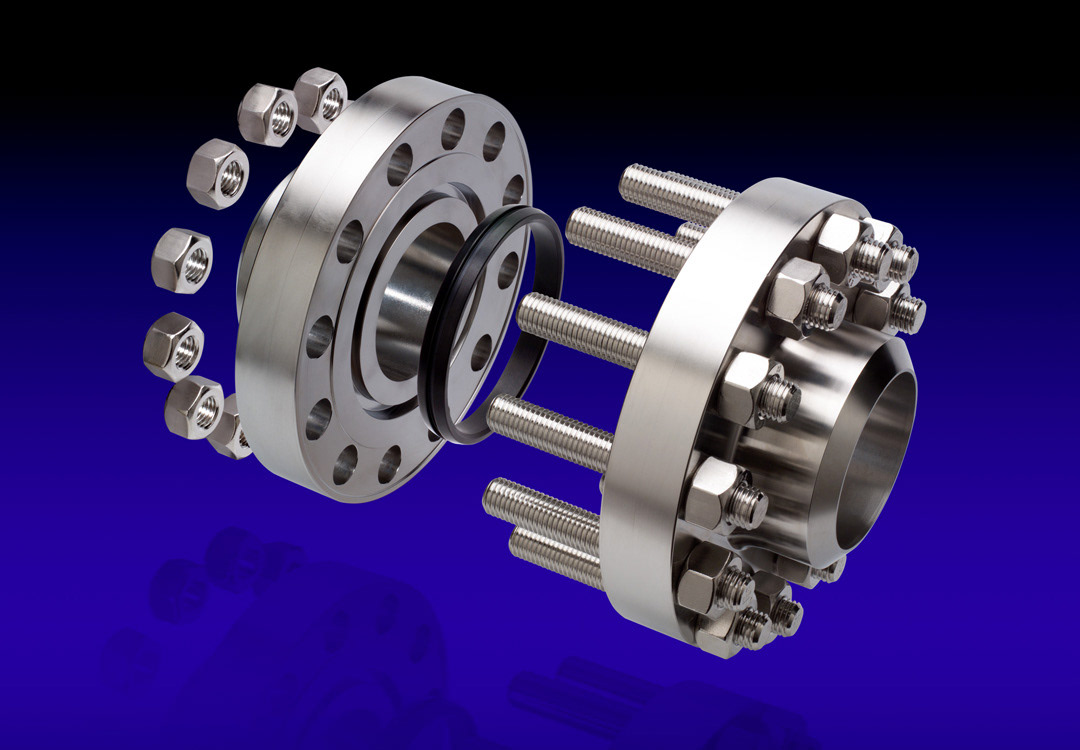
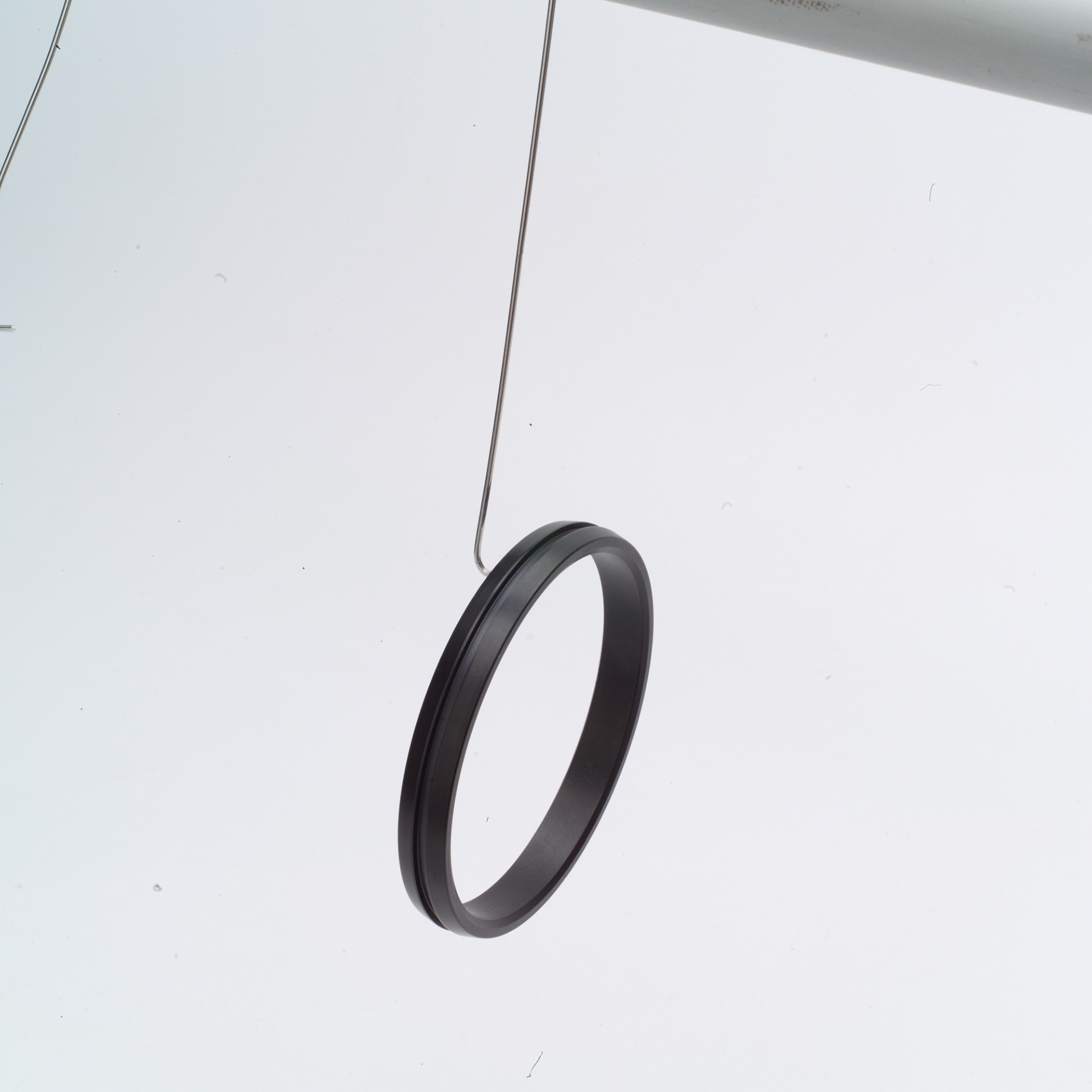
Since the seal ring (the black ring in the centre) is a key element, it was decided to show an exploded view. When the connector is fully assembled, you cannot see the seal ring, so this was a way of illustrating the whole 'workings' of the connector.
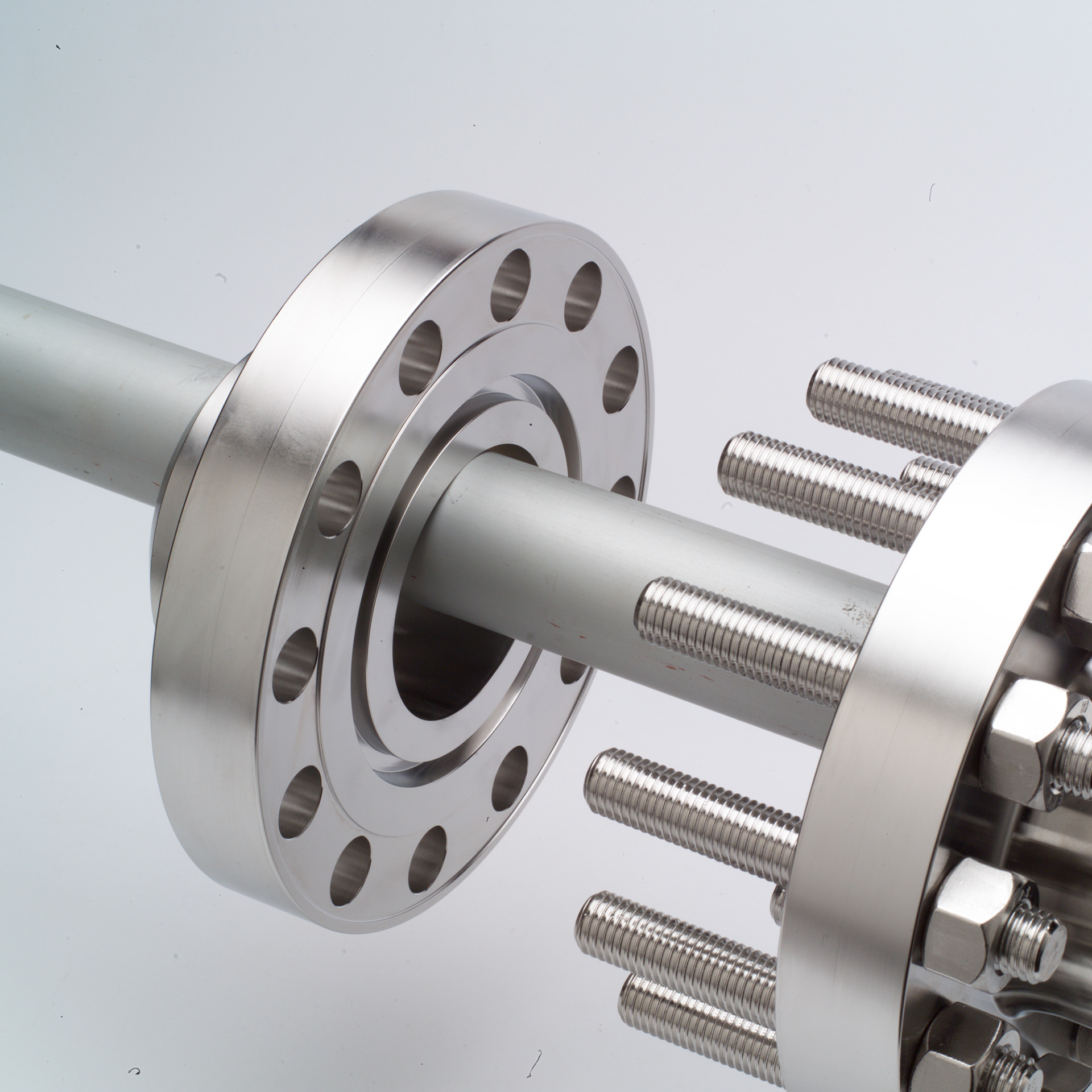
First of all, the individual parts of the connector were photographed.
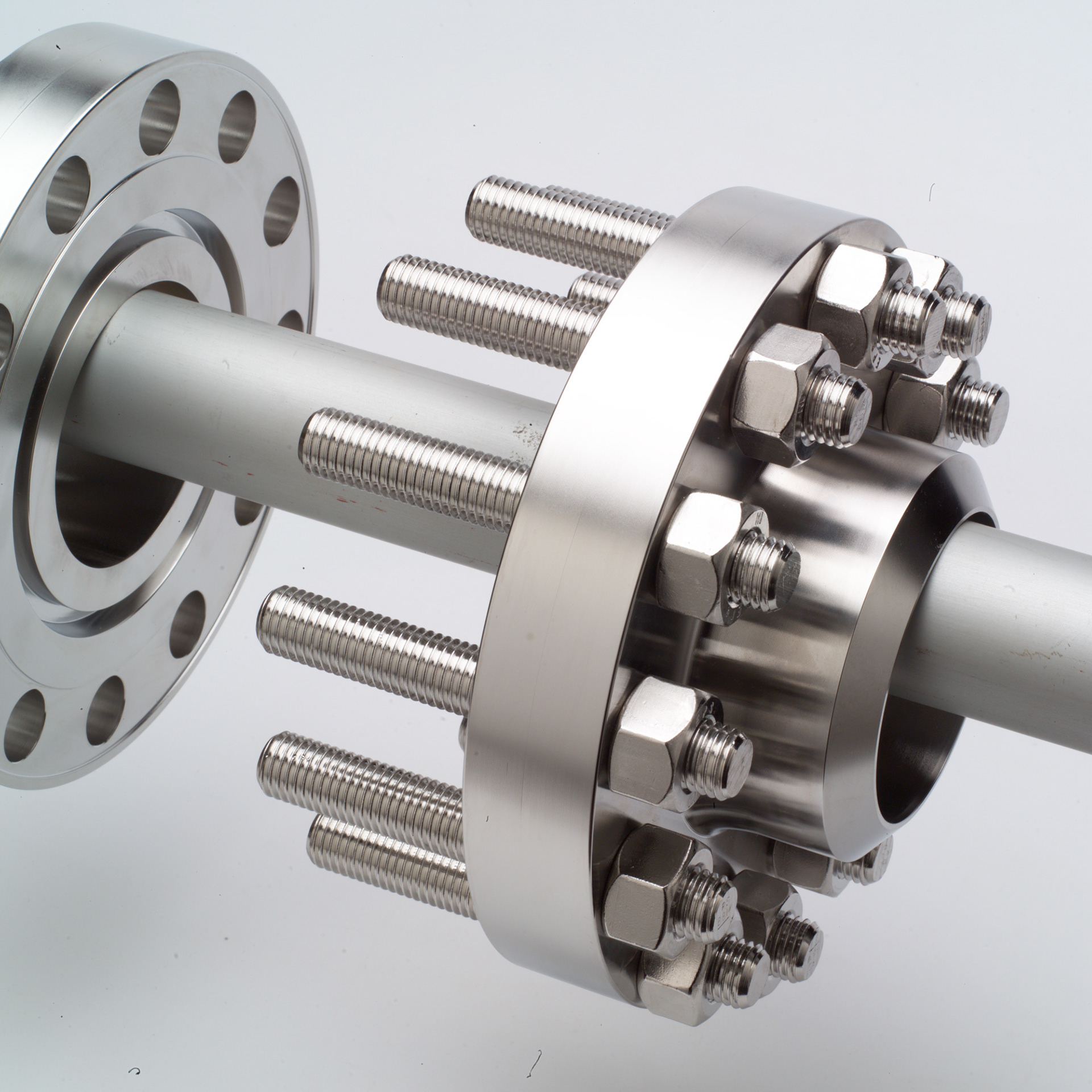
Since the flanges had to line up along their axes, they were positioned on an aluminium tube for support, which ensured correct alignment.
This shows the first flange in position for its photograph.
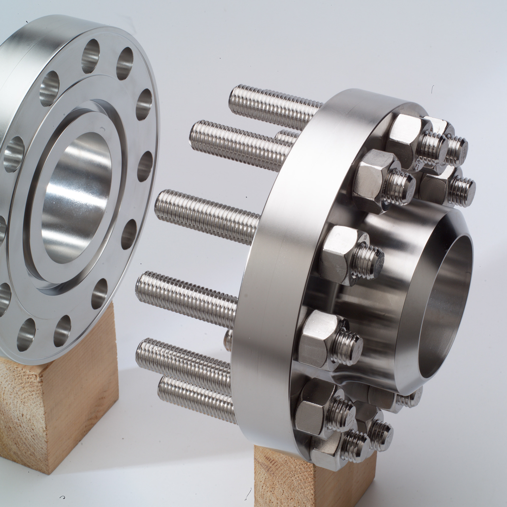
This shows the second flange in position for its photograph.
Luckily, the bolts sat in exactly the right position without having to be propped up or suspended, etc.
However, the aluminium tube is obscuring the bores of the flanges.
Time for another couple of shots!
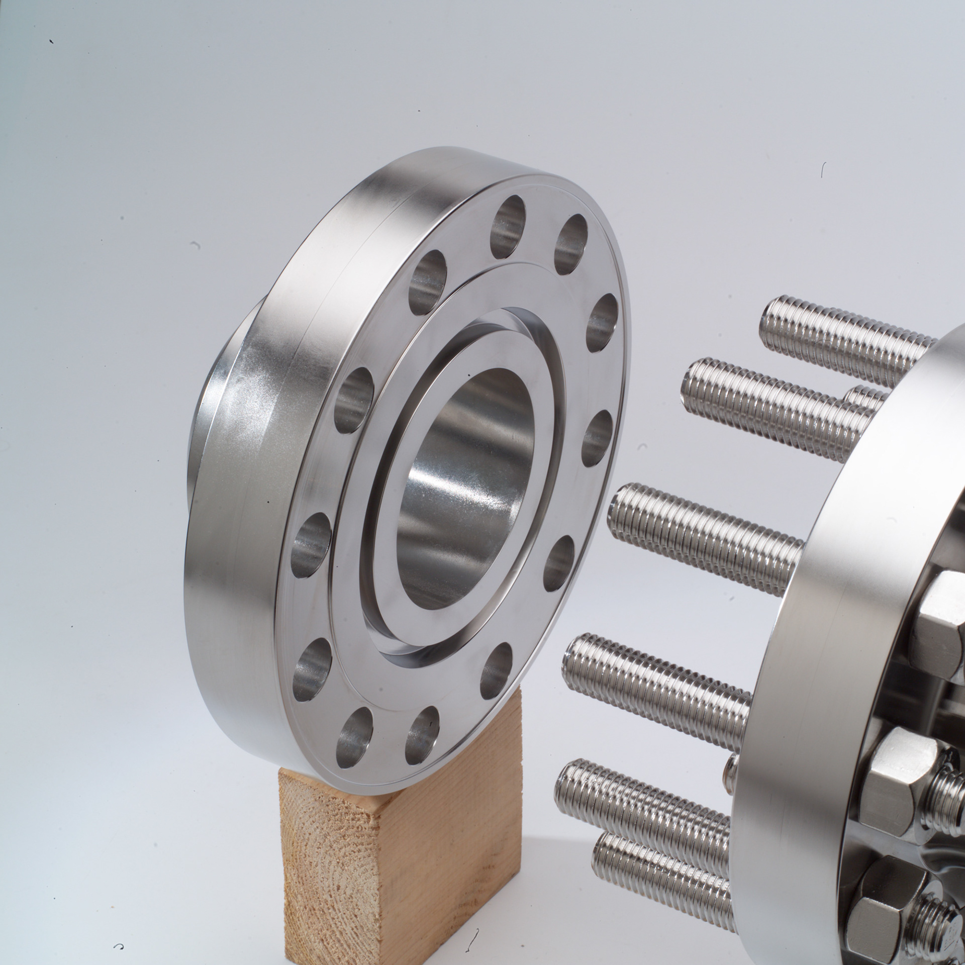
Here the aluminium tube has been removed and wooden blocks now support the flanges.
This gives a clear view of the bore in the first flange.
This shot is for the bore in the second flange.
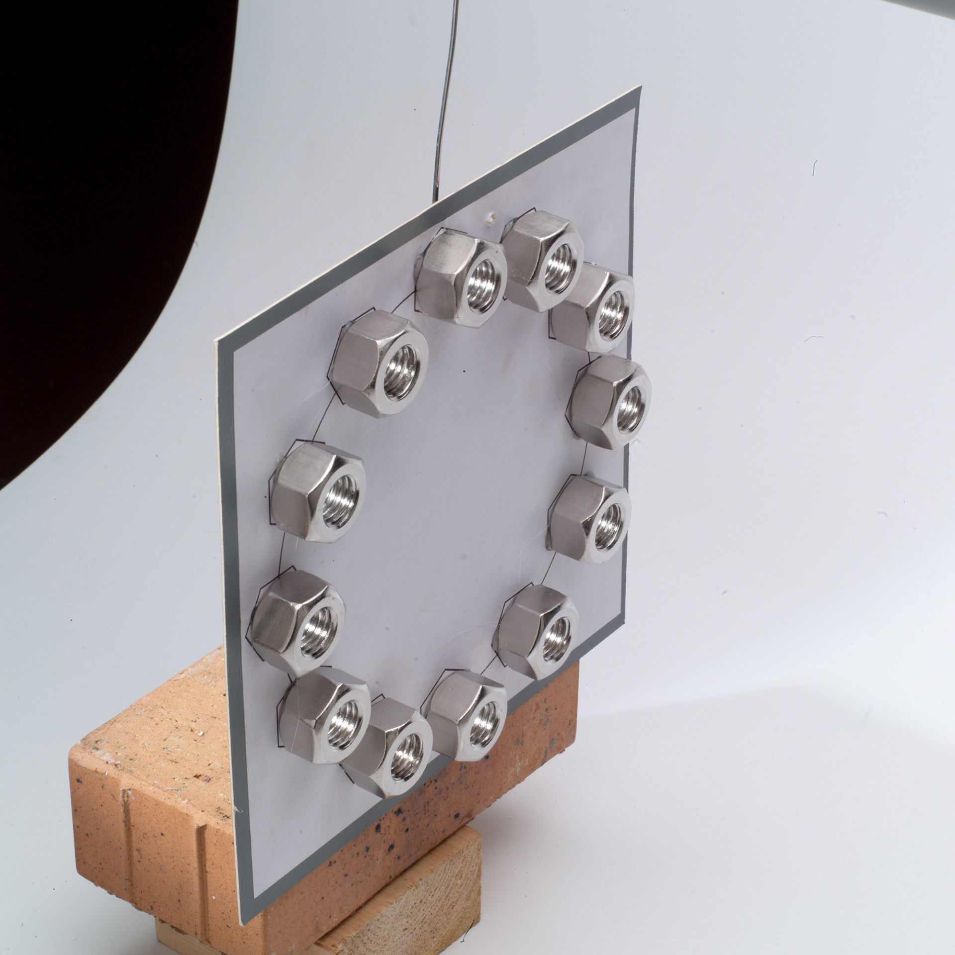
The nuts were hot glued to a piece of stiff card, having first marked out their radial positions for correct placement.
The card was then positioned where the nuts would be to line up with the bolts. It was suspended from a stiff wire, and the bricks were used to keep the card and nuts vertical and stop them from leaning over at an angle.
Finally, the seal ring was photographed, again suspended by wire in the correct position to line up with the other parts of the connector.
Now that each element has been photographed, it's time to put them all together!
We have four elements: the nuts, the first flange, the seal ring, and finally the second flange with the bolts. We also have clear views of the bores without the aluminium tube.
Using standard Photoshop (PS) techniques, each part was cut out to eliminate any background. The clear bores were superimposed on to their respective flanges. Each element was placed on its own layer in PS, and carefully aligned to ensure proper perspective. The blue/black background was created in PS, and the 'reflection' is the main composite repeated, re-positioned and faded.
This shot works because of the accurate placement and perspective of the various parts, and the consistent lighting.
If you tasked 6 photographers with this project, they would have done it six completely different ways... I'm sure! This happens to have been my way.